|
 |
 |
 |
||||||||
 |
 |
 |
||||||||
 |
 |
|||||||||
|
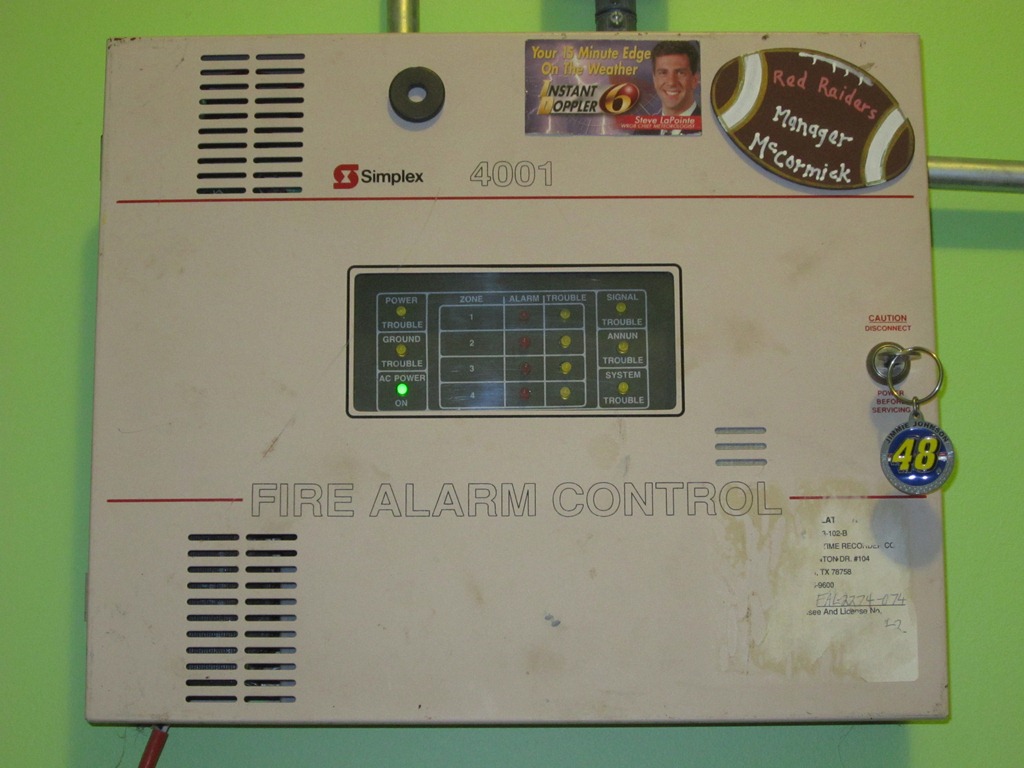
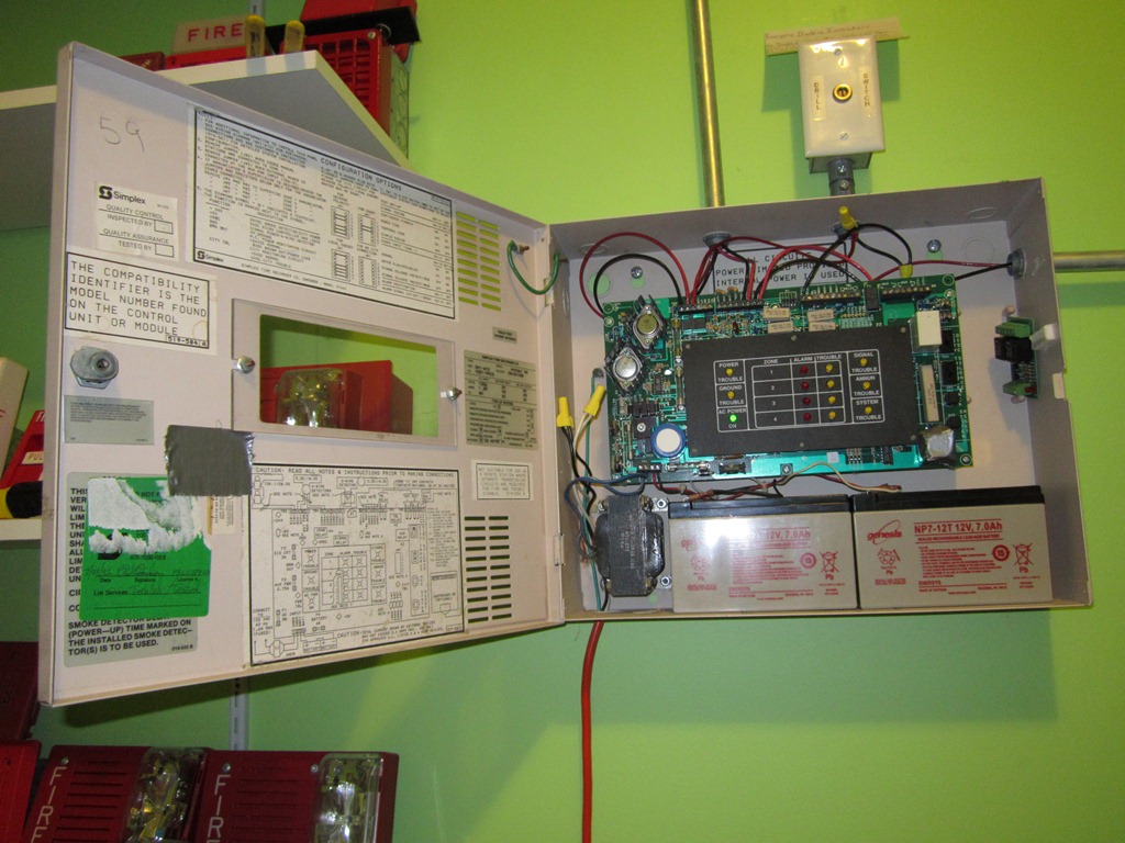
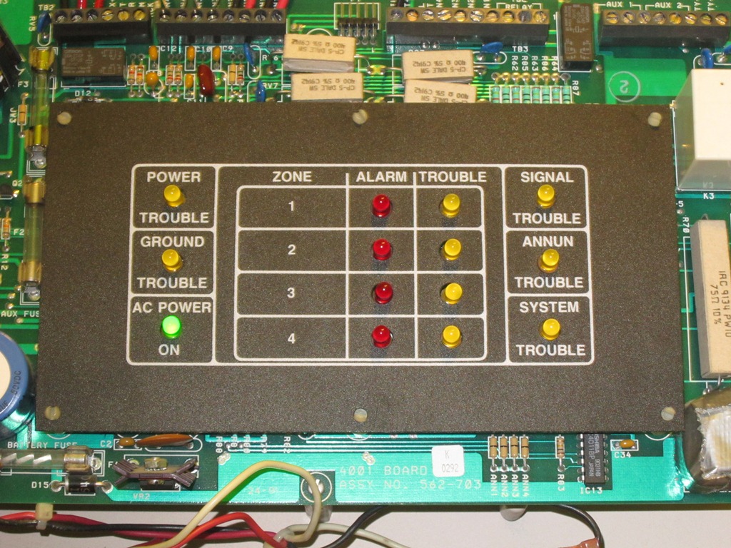
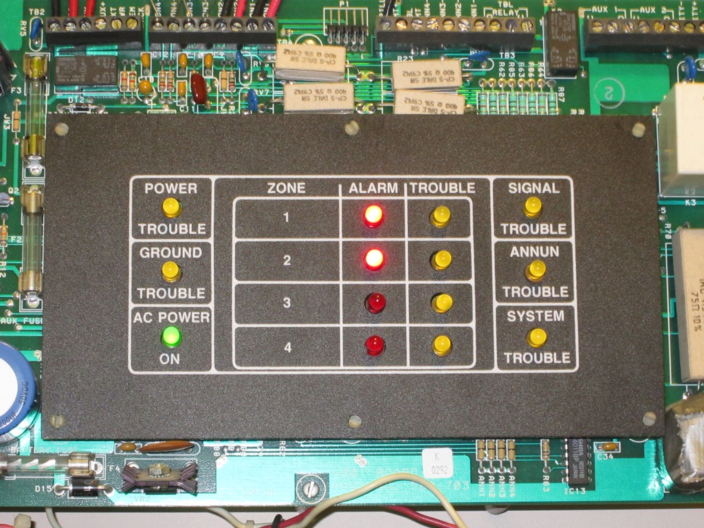
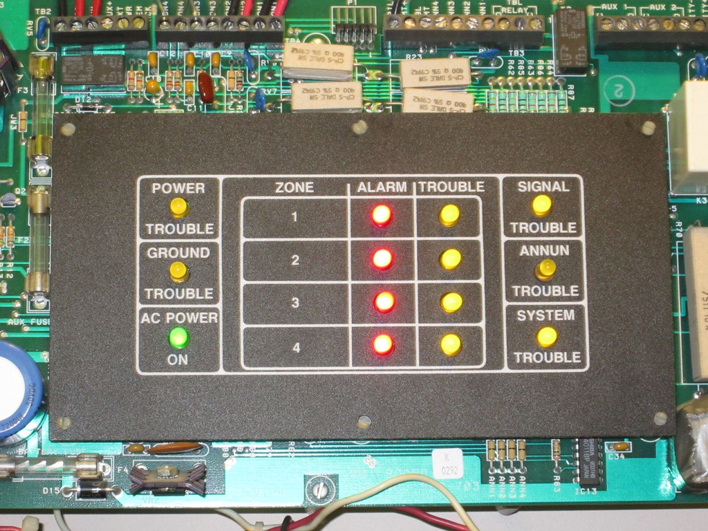
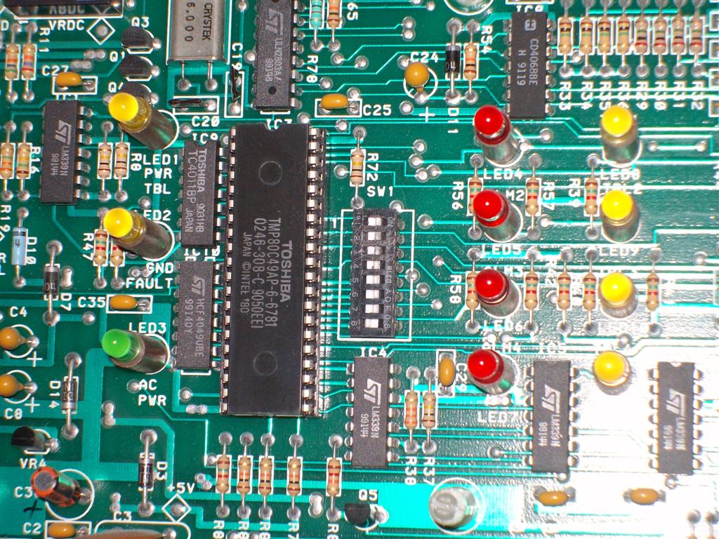
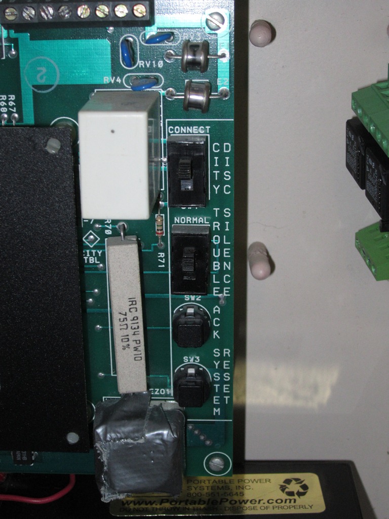
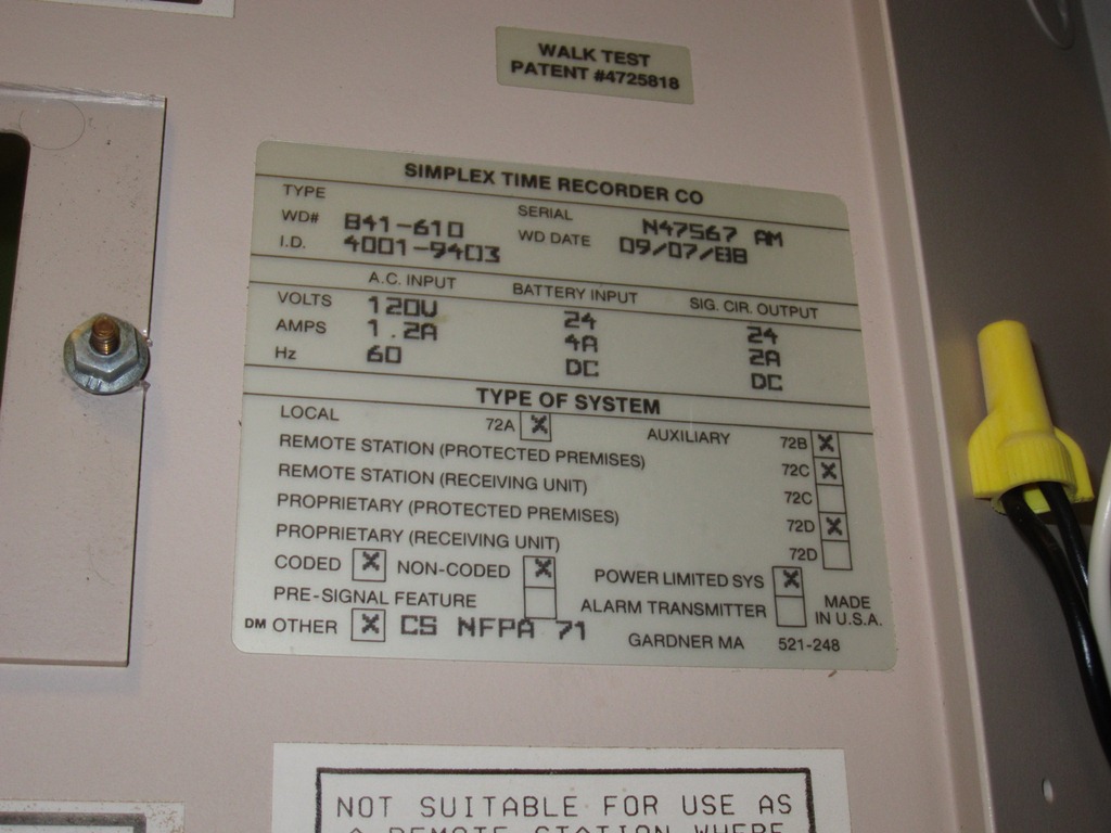
In July of 2005, I bought a Simplex 4001 Fire Alarm Control Panel (FACP) on eBay. The main purpose of this device is to alert people in a public building of the possibility of a fire. A typical fire alarm system may contain, but are not limited to, manual pull stations, smoke detectors, heat detectors, and/or a sprinkler system. These are known as the initiating devices. The purpose of these devices is to detect a fire condition either automatically (activation of smoke/heat detectors or sprinklers) or manually (a person activating a pull station). Other important devices in a system are the notification appliances, or signals. These devices include, but are not limited to, strobe lights, incandescent lights, horns, bells, or speakers. When an initiating device detects a fire condition (smoke, extreme heat, or when a pull station has been activated) a signal will be sent to the fire alarm panel, which will register the alarm and activate the notification appliances. The way this particular panel indicates alarm conditions is by flashing a red LED on the panel and sounding the notification appliances (the internal buzzer does not sound for alarms unless programmed for a sprinkler system setup). After the building has been evacuated, the appropriate personnel will open the panel. He or she will then silence the alarms by pressing the acknowledge button (ACK). They will then investigate what caused the alarm. If it is caused by a detector of some sort they will find the source of the problem, fix it, and wait for the area to be free of any smoke or heat. If a pull station was activated, they would check the immediate area for fire or smoke and reset the pull station. Once the source of the alarm has cleared, they will then press SYSTEM RESET. Upon pushing this button, all of the LEDs will illuminate for 2 seconds and the local panel buzzer will sound for 1 second. After about 5 seconds, the system should be completely reset. Besides alarms, the system also detects trouble conditions. A trouble condition exists if there is a fault or an opening somewhere within the circuitry of the system or if there is any other abnormal condition detected within the system. Any amber LED lit indicates a trouble condition. During a trouble condition, the notification appliances will not activate, but the local panel buzzer will sound a steady tone. To silence the tone, he or she will flip the switch labeled TROUBLE SILENCE to the down position, after which, the proper personnel will correct the problem. Once the problem has been corrected, the local panel buzzer will resound and the SYSTEM TROUBLE LED will disappear. The person operating the panel will then flip the trouble silence switch back to the up position. Once in the up position, the local panel buzzer will stop sounding and the system is automatically returned back to normal, without needing to be reset. Of course, none of this could have happened without programming. Behind the cover of the LED labels, there is a chip that consists of 8 switches. Each switch, or group of switches, affects the way in which the panel functions. The switches are either in the on or off position. Group 1 (switch one) is for testing purposes, group 2 (switches 2 and 3) affects signal coding. Each different combination of positions of the switches will change the pattern of the alarm signals. Both switches in the "on" position will indicate continuous operation. When both switches are off, you have simple coding, where as the number of pulses (.5 second pulses) indicates the zone in alarm. When switch 2 is off when switch 3 is on, you have a March Time coding which has a .25 second pulse a .25 second pause, and repeat. When switch 2 is on while switch 3 is off, the circuit will be temporal coded. Today’s version of the Temporal Code (also known as code-3) is a .5 second pulse, a .5 second pause, .5 second pulse, a .5 second pause, .5 second pulse, and a 1.5 second pause, and repeat. However, this panel’s temporal code has a .5 second pulse, a .5 second pause, .5 second pulse, a .5 second pause, .5 second pulse, and a 2.5 second pause, and repeat. Group 3 (switch 4) indicates a coding on zone 1. If this is selected, you cannot silence an alarm on zone one until the code transmission (usually from a coded pull station) is complete. Group 4 (switches 5 and 6) select the options for water flow and silence inhibit. Water flow is only for use with sprinkler systems to detect water flow. Silence inhibit prevents the panel from being silenced for a certain amount of time which can be set for either 1 or 3 minutes. Group 5 (Switch 7) is for alarm verification. If turned on, when a Simplex brand smoke detector is activated, the panel begins a 30 second timer to see if another device in that zone is activated. If not, it begins a 15 second reset cycle. After this it goes into a 2 minute confirmation period. If the device does not reactivate, the system returns to normal. If at any time during any of these cycles another device is activated, the panel will automatically go into alarm mode. Finally, group 6 (switch 8) is for signal cutout. If selected, if after 10 minutes of an alarm initiation the panel has not been silenced, the signals will silence automatically. Finally, some miscellaneous notes. This panel is able to be connected to the city fire department relay so that if it goes into alarm it automatically summons the fire department. However, that option is controlled by plugs and not with the switches above. There is a switch above the trouble silence switch that allows this to be temporary disconnected for maintenance issues (CITY DISCONNECT). If disconnected, the system will go into trouble until the switch is placed back in the "up" (normal) position. And that is the Simplex 4001 fire alarm control panel! |
| [Fire Alarms] [Fire Alarm Collection] [Grade School Fire Alarms] [College Fire Alarms] |
|
© 2014-2016 FAZone |